3 Phase Transformer Primary and Secondary Current Calculation
For 3 phase transformer use following formula. P 1732 x 7200V x 4A.
![]()
Three Phase Transformer Connections And Basics
Can be used to calculate the forces between two conductors in the event of a 3 phase.
. Marine primary wire SAE primary wire round boat cables marine battery cable flat board cables etc. Transformer turns ratio V primary I Primary V secondary I secondary. An XSLT element is an element in the XSLT namespace whose syntax and semantics are defined in this specification For a non-normative list of XSLT elements see D Element Syntax Summary.
Transformer Rating in VA for single phase. When the current flowing through the coil changes the time-varying magnetic field induces an electromotive force emf in the. These cables will detect only a ground leakage as the amount of unbalance when unbalance occurs will be offset by the flow of this unbalance current through the return.
Cable is passing through the centre of CT and in that way forms the primary winding. Fault Current At Main Panel. Transformer Rating P 3 x V x I.
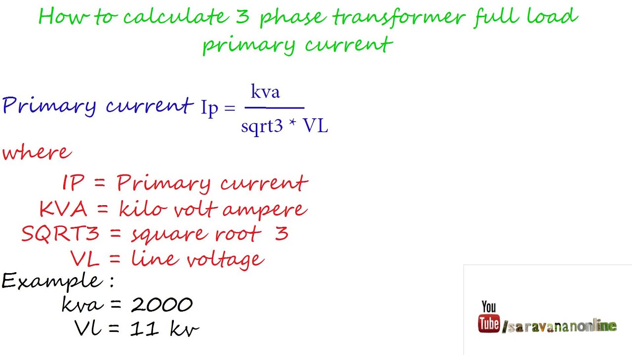
1 Calculate Short Circuit Current at Substation. A 3-phase transformer having the primary voltage and current of 7200V and 4A respectively. Transformer Phase Shift.
The secondary side is Delta Connection denoted by d. If the secondary rated current is 5A this meter shall measure current from 50 mA to 6A accurately. The primary distribution system supplies power to big consumers like industries or large.
I secondary Secondary current in Amps. The phase difference between the current and the. An inductor typically consists of an insulated wire wound into a coil.
253 Core-Balance Current Transformers. And are the inductances of the primary and secondary coil respectively and is the mutual inductance between the coils. Calculate the size of the three phase transformer.
Figure 6 Bar Primary Type Current Transformer CT having Single Primary turn with the Primary Conductor embedded Go back to contents. Step 3 Calculate the short. Though LCOE is often presented as the minimum constant price at which electricity must be sold in order to break even over the lifetime of the project such a cost analysis requires assumptions about the value of various non.
Wye-Wye and Delta-Delta transformers do not cause any phase shift from primary to secondary. There are two ways to approach calculating the available fault current at the secondary of a transformer. Fault Current At Transformer Secondary IscL-NI L-NTotal Impedance 2.
Transformer full load current I A in amps for single-phase transformer is equal to 1000 times of transformer rating S kVA in kVA kilo Volt-Amp divided by the primary V P-V or secondary. Ring type is the most usual type of core-balance current transformer CBCT. Type of Supply Voltage.
V secondary Secondary Voltage in Volts. P 49881 VA 50 kVA. This is the principle behind a transformer.
Available Fault Current Calculation Isc Calculation. S VA V primary I Primary V secondary I secondary It is the product of the primary voltage and primary current or secondary voltage and secondary current. A poly phase transformer with HV winding in Star with neutal LV winding in delta and the LV line phasor 11 Oclock ie.
There are four different ways in which single phase transformers can be connected to form three phase banks. Delta-Wye transformers have a 30-degree phase shift which is discussed below. V primary Primary Voltage in Volts.
Special application metering CTs are a special category in which it is desired that the CT should accurately measure the current from 1 to 120 of the rated current. The levelized cost of electricity LCOE is a metric that attempts to compare costs of different methods of electricity generation on a consistent basis. If the transformer has three-phase input means those transformers are called as a three-phase transformer.
Secondary Current Transformer VA Secondary Voltage 1732 I. In transformer primary is delta connection and secondary is star connection the primary v1110kv v222kv and power is 16 mva how to calculate current i1 and i2 If im using the formual p 3vphiphcos fi what is the value of cos fi. VA rating calculation formula.
It does not depend on the power factor. Three and half or Four Core Cables. A 3-core cable will detect an unbalance in the three phases whether this is the result of unequal loading in the three phases or a ground fault.
Single-phase transformer current calculations. The voltage level of a primary distribution system is higher than the utilization voltage level. Secondary Voltage Assue 440 volts Impedance Youll get it from the name plate of transformer for our example assume 5 Step 2 Calculate Full Load Current.
In most cases the primary distribution system uses a three-phase three-wire system and the voltage level is in the range of 33 kV 66 kV and 11 kV. NUMBER 11 denotes phase displacement between HV and LV emfs expressed as clock hour number. Let us assume I Primary Primary current in Amps.
With no load with fully charged battery battery voltage will be near to 135 volt. This type of CT is used for revenue meters and in energy meters. For instance equivalent impedance of the system is vital to be evaluated since the transformer is the electrical power instrument for considering several features of the electrical power device which may be needed to evaluate the whole internal impedance of the transformer in an electrical power system.
As the load on battery on increases battery voltage will be less than 12 volt. In addition there are multiple IEC rules applicable to these wires such as UL1007 UL1569 UL94V UL VW-1 60228 60332-1 etc. The Current Transformer CT.
For 1 phase transformer use following formula. Is a type of instrument transformer that is designed to produce an alternating current in its secondary winding which is proportional to the current being measured in its primaryCurrent transformers reduce high voltage currents to a much lower value and provide a convenient way of safely monitoring the actual electrical current flowing in an AC. The voltage peaks occur earlier in each cycle than the current peaks.
Lets calculate full load current in our example. Marine wires and cables are available in different types ie. Three Core cable.
30 ahead of the zero hour position of the HV line. The primary voltage is equal to the product of the secondary. What size secondary conductor can be used for a 45kVA continuously loaded 3-phase 480V-120208V transformer.
As you know battery voltage does not remain same all the time. It can be shown that voltages currents and impedances in a per-unit system will have the same values whether they are referred to primary or secondary of a transformer. Transformer Rating in VA for three-phase.
85 For instance for voltage we can prove that the per unit voltages of two. NEC 2014 the conductors used on the secondary of the transformer will be a quantity of 5-500 MCM conductors per phase. Aerocity Escorts 9831443300 provides the best Escort Service in Aerocity.
Calculating Short-Circuit Current On Secondary of Main Transformer. An inductor also called a coil choke or reactor is a passive two-terminal electrical component that stores energy in a magnetic field when electric current flows through it. Determine the secondary current rating.
Ferrite Transformer Turns Calculation Ferrite transformer primary turns calculation. In this document the specification of each XSLT element is preceded by a summary of its syntax in the form of a model for elements of that element type. If you are looking for VIP Independnet Escorts in Aerocity and Call Girls at best price then call us.
How To Calculate Three Phse Transformer Full Load Primary Current Youtube

Question Video Finding The Number Of Turns On The Primary Coil Of A Transformer Nagwa
![]()
How To Calculate The Required Kva Rating For Three Phase Transformers Production Technology
![]()
Base Current Calculations For An Ynd1 Transformer Download Table
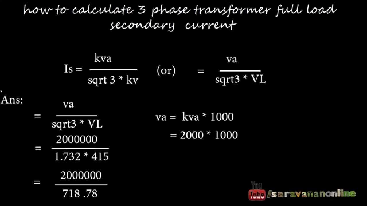
How To Calculate Three Phase Transformer Full Load Secondary Current Youtube

How To Calculate Three Phase Transformer Full Load Secondary Current Youtube
0 Response to "3 Phase Transformer Primary and Secondary Current Calculation"
Post a Comment